Input File
The MAP++ input file define the mooring properties, material definitions, connections between lines, and identify lines anchored or attached to a vessel.
We use the extension <*.map> to identify the MAP++ input file.
The sample MAP++ input deck and relevant commands are defined on this page.
Baseline Example
The baseline example below is a template on how properties are defined in MAP++:
--------------- LINE DICTIONARY ----------------------------------------------
LineType Diam MassDenInAir EA CB CIntDamp Ca Cdn Cdt
(-) (m) (kg/m) (N) (-) (Pa-s) (-) (-) (-)
mat_1 0.25 320.0 9800000000 1.0 -999.9 -999.9 -999.9 -999.9
mat_2 0.30 100.0 980000000 1.0 -999.9 -999.9 -999.9 -999.9
--------------- NODE PROPERTIES ----------------------------------------------
Node Type X Y Z M B FX FY FZ
(-) (-) (m) (m) (m) (kg) (mˆ3) (N) (N) (N)
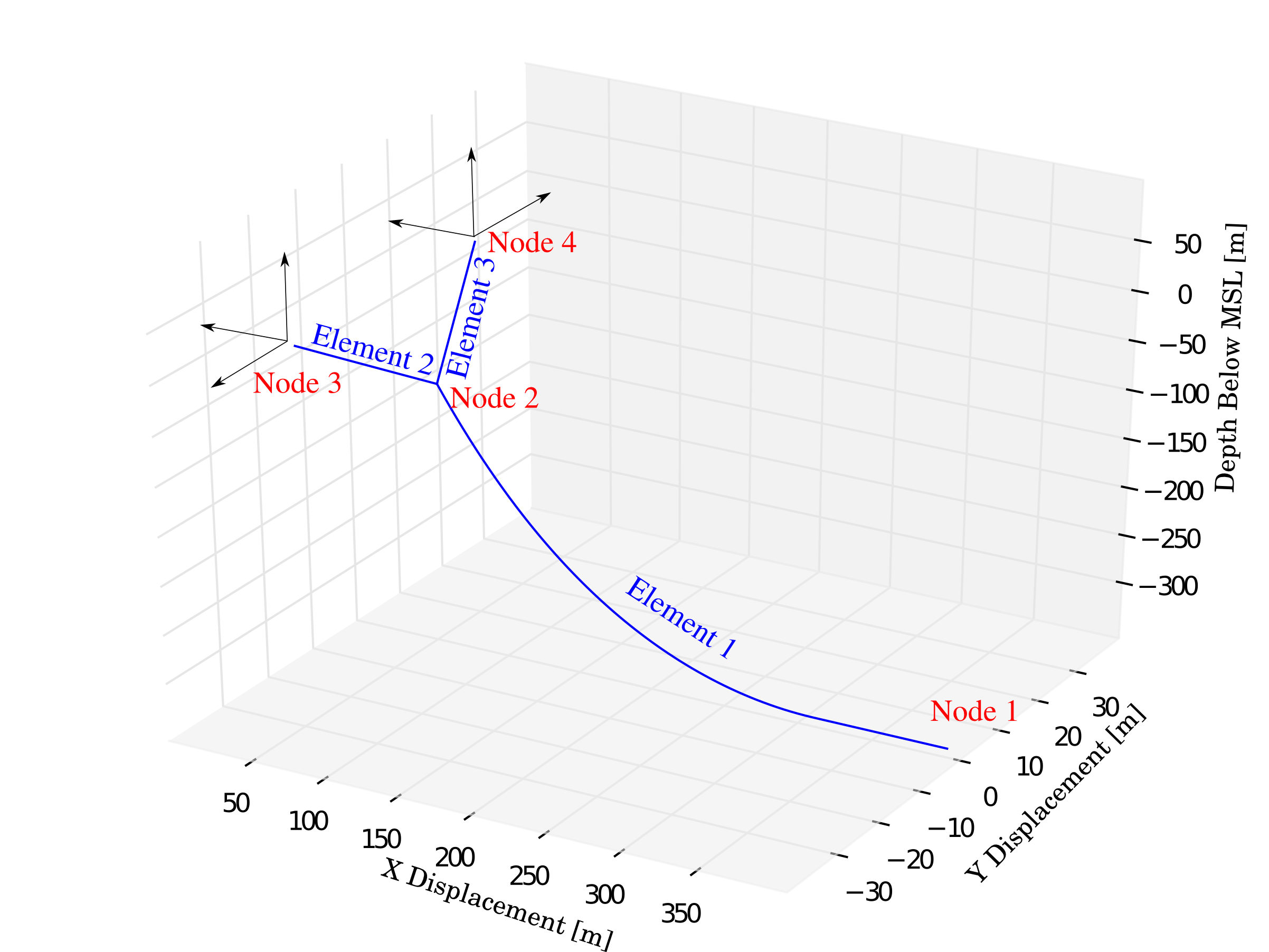
1 fix 400 0 depth 0 0 # # #
2 connect #90 #0 #-80 0 0 0 0 0
3 vessel 20 20 -10 0 0 # # #
4 vessel 20 -20 -10 0 0 # # #
--------------- LINE PROPERTIES ----------------------------------------------
Line LineType UnstrLen NodeAnch NodeFair Flags
(-) (-) (m) (-) (-) (-)
1 mat_1 450 1 2 altitude x_excursion
2 mat_2 90 2 3 tension_fair
3 mat_2 90 2 4
--------------- SOLVER OPTIONS------------------------------------------------
Option
(-)
outer_tol 1e-5
repeat 120 240
The space preceeding repeat 120 240 indicates that line is a comment and is ignored by MAP++. Executing this input file produced the mooring geoemtry illustrated here:
Note
Environmental properties like water depth, sea density, and gavity constant are set by the calling program. They are purposely absent in the MAP++ input file to prevent force imbalances from coefficient mismatches.
The MAP++ input file is divided into four sections:
- LINE DICTIONARY: Defines the material properties of the line.
- NODE PROPERTIES: Defines boundary constraints and extensional limits.
- LINE PROPERTIES: Associates a line with material properties and connectivity between nodes.
- SOLVER OPTIONS: Run-time options to engage different solve strategies.
Line Dictionary
| Variable | Definition | ||
|---|---|---|
LineType |
User–defined name [-] | |
Diam |
Material diameter [m] | |
MassDenInAir |
Mass density in air [kg/m^3] | |
EA |
Element axial stiffness [N/m] | |
CB |
Cable/seabed friction coefficient [-] | |
CIntDamp |
Unused | |
Ca |
Unused | |
Cdn |
Unused | |
Cdt |
Unused | |
Node Properties
| Variable | Definition |
|---|---|
NODE |
Node number (sequential) |
TYPE |
Type of node, which can be one of
FIX, CONNECT, or VESSEL.Vessel implied the node motion is prescribed.
|
X |
Global \(x\) coordinate if node is
FIX or CONNECT [m].Local \(x\) cooridinate relative to vessel if node is
VESSEL [m].Connect nodes must be preceeded by a # is indicate this is as an initial guess. |
Y |
Global \(y\) coordinate if node is
FIX or CONNECT [m].Local \(y\) cooridinate relative to vessel if node is
VESSEL [m].Connect nodes must be preceeded by a # is indicate this is as an initial guess. |
Z |
Global \(z\) coordinate if node is
FIX or CONNECT [m].Local \(z\) cooridinate relative to vessel if node is
VESSEL [m].Connect nodes must be preceeded by a # is indicate this is as an initial guess. |
M |
Point mass applied to the node [kg].
The force appled to the node is \(M\times g\) applied in the direction of gravity.
|
B |
Displaced volume applied to node [m^3].
The force applied is \(B\times \rho \times g\) applied opposite of gravity.
|
FX |
\(x\) direction external force applied to
CONNECT node [N].VESSEL and FIX must use # to indicate iterated value.# can be preceeded by user–suplied initial guess to speed convergence. |
FY |
\(y\) direction external force applied to
CONNECT node [N].VESSEL and FIX must use # to indicate iterated value.# can be preceeded by user–suplied initial guess to speed convergence. |
FZ |
\(z\) direction external force applied to
CONNECT node [N].VESSEL and FIX must use # to indicate iterated value.# can be preceeded by user–suplied initial guess to speed convergence. |
Line Properties
| Variable | Definition |
|---|---|
Line |
Line number (sequential). |
LineType |
Line type. Must be one type defined in LineType from dictionary. |
UnstrLen |
Unstretched line length [m]. |
NodeAnch |
Anchor node number |
NodeFair |
Fairlead node number |
Flags |
Line flag. Can include any command included in Flags |
Flags
Flags are applied to individual lines as indicated in the ‘LINE PROPERTIES’ section of the input file above. These flags control the output text stream:
| Variable | Definition |
|---|---|
GX_POS |
global X fairlead position [m] |
GY_POS |
global Y fairlead position [m] |
GZ_POS |
global Z fairlead position [m] |
GX_A_POS |
global X position of anchor [m] |
GY_A_POS |
global Y position of anchor [m] |
GZ_A_POS |
global Z position of anchor [m] |
GX_FORCE |
global X fairlead force [N] |
GY_FORCE |
global Y fairlead force [N] |
GZ_FORCE |
global Z fairlead force [N] |
H_FAIR |
horizontal (XY plane) fairlead force [N] |
H_ANCH |
horizontal (XY plane) anchor force [N] |
V_FAIR |
vertical (Z axis) fairlead force [N] |
V_ANCH |
vertical (Z axis) anchor force [N] |
TENSION_FAIR |
fairlead force magnitude, [N] |
TENSION_ANCH |
anchor force magnitude, [N] |
X_EXCURSION |
line horizontal excursion [m] |
Z_EXCURSION |
line veritical excursion [m] |
AZIMUTH |
line azimuth angle with respect to the inertial reference frame [deg] |
ALTITUDE |
angle of declination at the fairlead [deg] |
ALTITUDE_ANCH |
line lift|off angle at the anchor [deg] |
The follow flags enable/disable features for each line they are applied to:
| Variable | Definition |
|---|---|
LINE_TENSION |
line tension force magnitude at fairlead [N] |
OMIT_CONTACT |
ignore seabed boundary and treat line as freely hanging |
LINEAR_SPRING |
model the line as a linear spring. Intended for taut lines |
LAY_LENGTH |
amount of line laying on the seabed [m] |
DIAGNOSTIC |
run diagonostics on line for each solve iteration |
DAMAGE_TIME |
time [sec] to disconnect fairlead from node. Not used |
Solver Options
Solver options are applied to the entire model domain.
| Variable | Definition |
|---|---|
HELP |
prints a list of options on the command line when MAP++ initializes |
INNER_FTOL |
inner loop function tolerance |
INNER_GTOL |
desired orthogonality between the function evaluations and Jacobian
column
|
INNER_XTOL |
inner loop consecutive iterate tolerance |
INNER_MAX_ITS |
maximum inner loop iterations |
OUTER_MAX_ITS |
maximum outer loop iterations |
OUTER_TOL |
outer loop tolerance |
OUTER_EPSILON |
Not used |
INTEGRATION_DT |
Not used |
KB_DEFAULT |
Not used |
CB_DEFAULT |
Not used |
OUTER_CD |
central difference Jacobian (outer loop solve only) |
OUTER_BD |
backward difference Jacobian (outer loop solve only) |
OUTER_FD |
forward difference Jacobian (outer loop solve only) |
LM_MODEL |
Not used |
PG_COOKED |
use the relaxation algorithm developed in [4] |
KRYLOV_ACCELERATOR |
use the Krylov accelerator algorithm developed in [5] |
REPEAT |
repeat the element/nodes defined in the input file by mirroring the
mooring pattern with a rotation about the Z-axis
|
REF_POSITION |
reference position |
Todo
The REF_POSITION options is disabled in MAP++ until this feature can be fully integrated into the program. The reference position is fixed at \(<0, 0, 0>\) until then.
Default Solver Options
| Variable | Definition |
|---|---|
INNER_FTOL |
1.0E-6 |
INNER_GTOL |
1.0E-6 |
INNER_XTOL |
1.0E-6 |
INNER_MAX_ITS |
500 |
OUTER_MAX_ITS |
500 |
OUTER_TOL |
1.0E-6 |
OUTER_EPSILON |
1.0E-3 |
OUTER_BD |
|
REF_POSITION |
<0.0 , 0.0 , 0.0> |